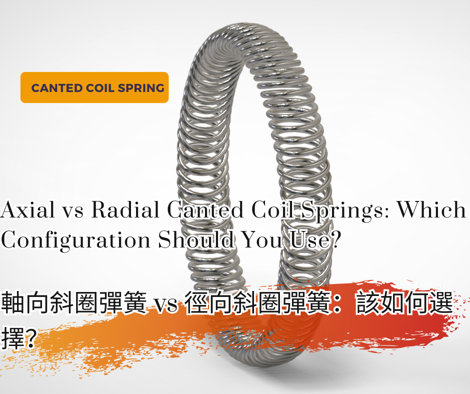
Axial vs Radial Canted Coil Springs: Which Configuration Should You Use?
Axial vs Radial Canted Coil Springs: Which Configuration Should You Use?
Choosing a canted coil spring is only the first step.
Once a designer has determined that a canted coil spring is suitable for an electrical contact, EMI/RFI shielding, grounding, or mechanical retention application, another important question follows:
Should the spring use an axial or radial configuration?
Axial and radial canted coil springs share the same basic spring technology, but they are designed to respond to compression in different directions. This difference affects how the spring is installed, how it interacts with the mating components, how the groove should be designed, and how contact force develops during assembly.
For electrical applications, spring orientation can also influence contact geometry, insertion behavior, electrical contact stability, and the way current travels through the contact interface.
This guide explains the difference between axial and radial canted coil springs, where each configuration is typically used, and what engineers should consider before selecting a spring orientation.
What Is a Canted Coil Spring?
A canted coil spring is made from a continuous series of coils arranged at a specific cant angle.
Unlike a conventional compression spring, the coils are intentionally inclined. When the spring is compressed, the coils deflect together and produce a controlled spring force.
One of the most useful characteristics of a canted coil spring is its relatively flat force versus deflection behavior within a defined working range.
This allows the spring to accommodate dimensional variation while maintaining a more consistent contact force.
Depending on the design, a canted coil spring can perform several functions:
- Electrical conduction
- EMI/RFI shielding
- Grounding
- Mechanical retention
- Latching and locking
- Component holding
- Spring energizing for sealing systems
For electrical applications, the continuous spring geometry also provides multiple contact points around or along the mating interface.
The spring can be manufactured as a welded ring for circular installations or as a continuous length for linear or complex groove geometries.
The next design decision is how the spring should deflect under load.
That is where axial and radial configurations become important.
What Is a Radial Canted Coil Spring?
A radial canted coil spring is designed so that its compression force acts in the radial direction of the spring ring.
In simple terms, the spring is compressed inward or outward across the radius of a circular assembly.
For a circular spring installed around a shaft or inside a bore, the radial compression direction is perpendicular to the centerline of the spring ring.
This makes radial canted coil springs a natural configuration for many cylindrical interfaces.
Typical examples include:
- Electrical connectors
- Pin and socket interfaces
- Shaft and bore assemblies
- Circular grounding contacts
- Mechanical retention systems
- Spring energized sealing applications
In a housing mounted configuration, the spring may sit inside a groove machined into a bore. When a pin, shaft, or mating component is inserted, the spring is radially compressed between the housing and the inserted component.
A similar principle can be used with a spring installed on the outside diameter of a shaft or piston.
The important point is not simply where the spring is located.
The defining characteristic is the direction in which the spring is designed to deflect.
How Radial Compression Works
Consider a circular connector consisting of a male pin and a female housing.
A radial canted coil spring can be installed in an internal groove inside the housing.
As the pin enters the bore, it contacts the spring and causes radial deflection.
The spring then applies contact force between the two mating components.
The basic relationship becomes:
Pin insertion
↓
Radial spring deflection
↓
Contact force
↓
Electrical and mechanical contact
Because the spring extends around the circumference, multiple coils can establish contact around the mating interface.
This can be useful where the design requires reliable circumferential contact within a compact annular space.
Typical Radial Canted Coil Spring Applications
Radial configurations are commonly considered when the mating components move along the axis of a cylindrical assembly while the spring provides contact force in the radial direction.
Examples may include:
- High current circular connectors
- EV battery and power connectors
- Industrial power connectors
- Robotic electrical interfaces
- Grounding contacts
- Cylindrical mechanical retention systems
- Shaft or piston mounted applications
The exact configuration still depends on groove geometry, required force, insertion behavior, electrical requirements, and available installation space.
What Is an Axial Canted Coil Spring?
An axial canted coil spring is designed so that its primary compression direction is parallel to the spring centerline.
Instead of being compressed primarily across the radius, the coils deflect in the axial direction.
Axial configurations are often associated with face mounted installations where two surfaces move toward each other and compress the spring.
Typical applications may include:
- Face contact interfaces
- Flange connections
- Electrical grounding interfaces
- EMI/RFI shielding
- Equipment housings
- Conductive enclosure interfaces
- Mechanical face retention
For example, an axial canted coil spring may be installed in a groove on one mating face.
When the second component is assembled against it, the spring is compressed axially.
This allows the spring to maintain contact between the two surfaces while accommodating dimensional variation and movement.
How Axial Compression Works
Consider two conductive housing surfaces that must maintain electrical continuity.
An axial canted coil spring can be positioned between the mating faces.
As the assembly closes:
Mating surfaces approach
↓
Axial spring compression
↓
Contact force develops
↓
Multiple conductive contact points are established
This configuration can be particularly useful when electrical bonding or EMI/RFI shielding must be maintained across a face interface.
Axial canted coil springs can also be incorporated into more specialized connector geometries where their coil movement and contact arrangement are used to control electrical and mechanical behavior.
For this reason, axial should not automatically be interpreted as meaning only a flat face mounted spring.
The actual spring behavior depends on the spring geometry, groove geometry, mating component, and direction of applied load.
Axial vs Radial Canted Coil Springs: Key Differences
The most fundamental difference between axial and radial canted coil springs is the intended direction of spring deflection.
| Design Factor | Axial Canted Coil Spring | Radial Canted Coil Spring |
|---|---|---|
| Primary compression direction | Parallel to spring centerline | Perpendicular to spring centerline |
| Common interface | Face or specialized connector interface | Shaft, pin, bore, cylindrical interface |
| Typical groove location | Face groove or application specific groove | Housing bore or shaft OD groove |
| Contact behavior | Axial loading between mating interfaces | Radial loading around mating interface |
| Circular electrical contact | Application dependent | Particularly suitable |
| Face electrical bonding | Particularly suitable | Application dependent |
| EMI/RFI shielding | Suitable | Suitable |
| Mechanical retention | Possible | Particularly useful in many cylindrical assemblies |
| Insertion behavior | Depends strongly on geometry | Often directly related to radial deflection during insertion |
| Tolerance accommodation | Good when designed within working range | Good when designed within working range |
This table provides a useful starting point, but spring orientation should not be selected from geometry alone.
The spring must be evaluated as part of the complete mechanical and electrical interface.
How Spring Orientation Changes Force Direction
The terms axial and radial describe more than the physical position of the spring.
They describe the direction in which the spring is intended to react to compression.
For a radial spring, the compression force acts along the radius of the spring ring and is perpendicular to the centerline.
For an axial spring, the compression force acts along the axis of the spring and is parallel to the centerline.
This distinction matters because the spring force ultimately becomes contact force against the mating component.
If the spring orientation does not match the intended movement and contact geometry, the spring may operate outside its preferred deflection range.
Possible consequences include:
- Excessive contact force
- Insufficient contact force
- High insertion force
- Poor spring retention
- Unstable electrical contact
- Accelerated wear
- Permanent spring deformation
The correct spring orientation therefore starts with a simple engineering question:
In which direction must the spring generate useful force?
Only after that question is answered should the groove and spring dimensions be finalized.
Axial vs Radial Groove Design
The groove is not simply a space used to hold the spring.
It is part of the spring system.
Groove dimensions influence:
- Installed spring deflection
- Spring retention
- Contact force
- Available movement
- Insertion and removal behavior
- Tolerance accommodation
- Electrical contact location
For this reason, an axial spring and a radial spring should not simply be placed into the same groove and expected to behave identically.
Radial Groove Design
A radial canted coil spring used in a cylindrical interface may be installed in:
- An internal housing groove
- An external shaft or piston groove
For a housing mounted design, the groove retains the spring while the mating shaft or pin compresses it radially.
For a shaft mounted design, the relationship is reversed.
Important dimensions may include:
- Groove diameter
- Groove depth
- Groove width
- Mating shaft or bore diameter
- Spring cross section
- Minimum installed deflection
- Maximum installed deflection
The designer should evaluate both minimum and maximum tolerance conditions.
If the spring is compressed too little at the largest clearance condition, contact force may become insufficient.
If it is compressed too much at the tightest tolerance condition, contact force and insertion force may become excessive.
Axial Groove Design
For a face mounted axial spring, groove depth and the final distance between the mating surfaces determine the installed spring deflection.
Important dimensions may include:
- Groove depth
- Groove width
- Mating face position
- Spring height
- Minimum assembly gap
- Maximum assembly gap
- Flatness and alignment of the mating surfaces
The spring must remain within its intended working deflection range throughout the expected dimensional variation of the assembly.
In electrical or EMI shielding applications, the groove must also allow the spring to maintain sufficient conductive contact with the relevant mating surfaces.
Tolerance Stack Up
Tolerance stack up is one of the most important considerations for both axial and radial canted coil springs.
The nominal assembly dimension alone is not enough.
Engineers should evaluate at least three conditions:
- Nominal condition
- Minimum spring compression condition
- Maximum spring compression condition
For a radial connector, tolerance stack up may include the housing bore, groove depth, pin diameter, plating thickness, spring dimensions, and concentricity.
For an axial interface, it may include groove depth, spring height, mating face position, flatness, coating thickness, and assembly compression.
The goal is to keep the spring inside an acceptable working deflection range under all realistic tolerance conditions.
This is one reason why the relatively flat force characteristic of a properly designed canted coil spring can be valuable in assemblies with dimensional variation.
Axial vs Radial Springs for Electrical Contact
For electrical contact applications, spring orientation affects more than mechanical fit.
The spring must maintain a reliable conductive path between the mating components.
Important electrical design factors include:
- Contact force
- Number of contact points
- Contact resistance
- Spring material
- Surface plating
- Mating surface material
- Current
- Temperature rise
- Vibration
- Mechanical cycling
Both axial and radial canted coil springs can be used in electrical applications when the spring, groove, material, plating, and mating surfaces are designed appropriately.
The correct choice depends on the complete current path and mechanical interface.
Radial Springs for Electrical Connectors
Radial canted coil springs are particularly intuitive in circular electrical connectors.
A spring installed around a pin or inside a bore can create multiple circumferential contact points between mating components.
This arrangement can provide:
- Compact electrical contact
- Multiple conductive paths
- Circumferential contact
- Mechanical retention
- Tolerance accommodation
- Repeatable insertion and removal
For high current applications, however, spring orientation alone does not determine current carrying capability.
Contact resistance, material, plating, contact geometry, spring force, heat generation, and the mating conductors must all be considered together.
Axial Springs for Electrical Contact
Axial canted coil springs can be useful when the required electrical contact force must act along an axial interface.
Face contacts are one obvious example.
However, axial spring configurations can also be engineered into specialized connector assemblies.
In some electrical contact designs, axial spring geometry can create different contact locations and electrical path lengths than a radial configuration. This can affect electrical resistance, heat generation, and current carrying performance.
The important engineering lesson is that the terms axial and radial should not be treated as simple labels for where the spring is installed.
The complete spring, groove, mating geometry, and electrical path must be evaluated together.
Contact Resistance and Spring Orientation
Low contact resistance depends on stable physical contact between conductive surfaces.
Spring orientation contributes to this by determining where and how the spring applies force.
However, neither axial nor radial orientation automatically guarantees lower contact resistance.
Contact resistance is affected by:
- Contact force
- Actual contact area
- Number of contact points
- Material conductivity
- Surface plating
- Oxidation
- Contamination
- Wear
- Temperature
- Vibration
A well designed radial spring can provide highly stable electrical contact in a cylindrical connector.
A well designed axial spring can provide equally valuable performance in a face contact or a specialized electrical contact assembly.
The relevant question is not:
Which orientation has the lowest resistance?
The better question is:
Which orientation creates the most stable electrical contact for this specific mating geometry and operating condition?
Insertion and Removal Force
Insertion force is especially important when a canted coil spring is used in a connector or removable mechanical interface.
In a typical radial pin and socket configuration, the mating pin contacts the spring during insertion and causes the coils to deflect.
The resulting insertion force depends on several factors:
- Spring force
- Spring geometry
- Amount of deflection
- Contact angle
- Surface finish
- Plating
- Lubrication, if applicable
- Mating component geometry
A spring with excessive contact force may produce an electrical connection that appears mechanically secure, but the connector may become difficult to assemble or service.
Excessive insertion force can also increase wear on the spring, plating, and mating surface.
Conversely, insufficient spring force can reduce mechanical retention and electrical contact stability.
The design target should therefore be a controlled balance between:
Electrical contact
Mechanical retention
Insertion force
Removal force
Wear life
This balance is especially important for connectors that will be repeatedly connected and disconnected during their service life.
Mechanical Retention and Latching
A canted coil spring can do more than conduct electricity.
Depending on the groove and mating geometry, the same spring may also provide mechanical retention.
In a cylindrical assembly, a radial spring can engage a mating feature on a pin or shaft to create a controlled holding or removal force.
This can allow one component to perform multiple functions:
- Electrical contact
- Grounding
- Mechanical retention
- Alignment
- Latching
In some applications, combining these functions can reduce component count and simplify the assembly.
However, electrical and mechanical requirements must be evaluated together.
Increasing spring force to improve retention may also increase insertion force and wear.
Changing groove geometry to create stronger latching may change spring deflection and electrical contact behavior.
The spring should therefore be designed as part of the entire interface rather than as an isolated component.
Axial vs Radial Springs for EMI/RFI Shielding
Canted coil springs can also be used to maintain conductive continuity across an enclosure or equipment interface for EMI/RFI shielding.
The choice between axial and radial orientation depends largely on the geometry of the shielding interface.
Axial EMI/RFI Shielding
An axial spring may be suitable when two conductive faces close toward each other.
Examples include:
- Covers
- Flanges
- Equipment panels
- Conductive face interfaces
- Enclosure joints
When the assembly closes, the spring is compressed and maintains conductive contact across the interface.
The ability to maintain contact despite dimensional variation can be particularly valuable where surface flatness or assembly tolerance makes a rigid contact difficult to maintain.
Radial EMI/RFI Shielding
A radial spring may be suitable for cylindrical shielding interfaces.
Examples include:
- Circular connectors
- Cylindrical housings
- Removable sleeves
- Grounding rings
- Rotationally symmetric interfaces
The spring can maintain multiple contact points around the circumference while accommodating dimensional variation between the mating components.
For both configurations, shielding performance depends on more than spring orientation.
Material, plating, spring spacing, contact force, groove geometry, surface condition, and the continuity of the complete enclosure must also be considered.
Axial vs Radial Canted Coil Springs for Vibration
Shock and vibration can cause microscopic movement between electrical contact surfaces.
Over time, this movement may contribute to wear, fretting, changes in contact resistance, and intermittent electrical behavior.
A properly designed canted coil spring can help maintain contact force as the mating components experience dimensional movement.
However, the orientation must match the direction and geometry of the interface.
For a cylindrical connector, a radial spring may maintain circumferential contact as the assembly experiences vibration.
For a face mounted interface, an axial spring may maintain compression between mating surfaces.
The important requirement is not simply that the spring remains physically installed.
It must continue to provide sufficient contact force throughout the expected movement of the assembly.
Material and Plating Considerations
Axial and radial orientation does not determine the correct spring material or plating.
Those decisions should be based on the mechanical, electrical, and environmental requirements of the application.
Ivex canted coil springs can be manufactured using materials such as:
- 302 Stainless Steel
- Hastelloy C276
- Elgiloy or equivalent high performance alloys
- 316 Stainless Steel
- Beryllium Copper
Depending on the electrical requirements, surface plating may also be considered.
Available plating options for canted coil spring applications can include:
- Silver
- Gold
- Nickel
- Tin
For example, silver plating may be considered where high electrical conductivity is important, while gold may be considered where long term surface stability and corrosion resistance are critical.
The correct combination should be selected based on current, contact resistance, environment, temperature, mechanical cycling, mating material, and expected service life.
When Should You Use a Radial Canted Coil Spring?
A radial canted coil spring should be considered when the design requires contact force to act radially across a cylindrical interface.
It is particularly suitable when:
- The assembly consists of a shaft, pin, piston, or cylindrical mating component
- The spring is installed inside a housing bore or around an outside diameter
- Circumferential electrical contact is required
- The mating component is inserted axially while the spring deflects radially
- Mechanical retention is required around a cylindrical interface
- The design requires multiple contact points around a circumference
Typical applications may include circular electrical connectors, EV power connections, grounding contacts, industrial equipment, and cylindrical retention systems.
When Should You Use an Axial Canted Coil Spring?
An axial canted coil spring should be considered when the required spring force acts primarily along an axial interface.
It may be particularly suitable when:
- Two mating faces move toward each other
- Face contact must be maintained
- EMI/RFI shielding is required across a flange or enclosure
- Electrical bonding is required between mating surfaces
- The design requires axial spring compression
- The contact geometry benefits from axial coil movement
Axial spring configurations may also be used in specialized electrical connector designs where the groove and contact geometry are engineered to achieve specific electrical and mechanical behavior.
Axial or Radial: A Practical Selection Guide
The following questions can help narrow the selection.
1. What Is the Direction of Required Contact Force?
If the useful contact force must act radially against a shaft, pin, or bore, a radial configuration is a natural starting point.
If the force must act between mating faces or along an axial interface, an axial configuration may be more appropriate.
2. How Do the Components Move During Assembly?
Determine whether the mating components:
- Slide into each other
- Close face to face
- Rotate
- Require repeated insertion
- Remain permanently assembled
The movement determines how the spring enters its working deflection range.
3. What Is the Available Groove Geometry?
The available installation space may strongly influence spring orientation.
Do not select a spring first and force it into an unsuitable groove.
The spring and groove should be developed as one system.
4. How Much Dimensional Variation Must the Spring Accommodate?
Calculate both minimum and maximum installed deflection.
Include manufacturing tolerances, plating thickness, alignment, thermal expansion, and expected wear where relevant.
5. Is the Spring Carrying Electrical Current?
If yes, evaluate:
- Current
- Contact resistance
- Temperature rise
- Material
- Plating
- Number of contact points
- Mating conductor
- Electrical path length
Do not select axial or radial orientation based only on mechanical fit.
6. Is Mechanical Retention Also Required?
If the spring must both conduct electricity and retain a mating component, the required insertion and removal forces should be defined early in the design process.
7. Is EMI/RFI Shielding Required?
Determine where conductive continuity must be maintained.
A face interface and a cylindrical interface may require very different spring and groove configurations even when both use the same canted coil spring technology.
Common Axial and Radial Spring Selection Mistakes
Choosing by Appearance Instead of Force Direction
The physical location of the spring does not by itself determine whether an axial or radial design is appropriate.
Start with the direction of useful spring force.
Designing Only at Nominal Dimensions
A spring that performs correctly at nominal dimensions may be over compressed or under compressed at tolerance extremes.
Always evaluate minimum and maximum installed conditions.
Treating the Groove as a Simple Retainer
The groove controls spring position and deflection.
Its dimensions directly influence spring force and contact behavior.
Ignoring Insertion Force
This is particularly important in removable radial connector designs.
A spring that produces adequate contact force may still create excessive insertion or removal force.
Selecting Orientation Based Only on Electrical Current
High current capability is determined by the complete electrical contact system.
Axial or radial orientation alone does not determine current carrying capability.
Ignoring the Mating Surface
The spring is only one side of the contact interface.
Surface material, plating, finish, geometry, and dimensional variation of the mating component can all influence performance.
Assuming Axial Always Means Face Mounted
Face mounted applications are a common use of axial springs, but specialized connector designs may also use axial canted coil springs in other geometries.
Always evaluate the actual spring deflection and contact path.
Information Ivex Needs to Recommend an Axial or Radial Canted Coil Spring
The most useful starting point is usually an assembly drawing.
When contacting Ivex Engineering, provide as much of the following information as possible:
- Assembly drawing
- Shaft, bore, or mating face dimensions
- Available groove dimensions
- Direction of component movement
- Required contact force
- Minimum and maximum spring deflection
- Required insertion force
- Required removal force
- Electrical current
- Maximum acceptable contact resistance
- Spring material requirements
- Plating requirements
- Mating surface material and plating
- Operating temperature
- Vibration and shock conditions
- EMI/RFI shielding requirements
- Mechanical retention requirements
- Required service cycles
If the groove has not yet been finalized, providing the surrounding assembly dimensions may be more useful than defining the spring dimensions too early.
Ivex Engineering can evaluate the application requirements and help determine whether an axial or radial canted coil spring configuration is more appropriate.
Spring dimensions, load, material, length, and surface plating can then be developed according to the actual operating conditions.
Frequently Asked Questions
What Is the Main Difference Between Axial and Radial Canted Coil Springs?
The main difference is the intended direction of compression.
A radial canted coil spring is designed to react primarily to compression along the radius of the spring ring, perpendicular to its centerline.
An axial canted coil spring is designed to react primarily to compression parallel to the spring centerline.
Is a Radial Canted Coil Spring Better for Electrical Connectors?
Radial canted coil springs are well suited to many cylindrical pin and socket connectors because they can provide circumferential contact around the mating component.
However, axial canted coil springs can also be used in electrical contact assemblies.
The correct choice depends on contact geometry, groove design, current path, force requirements, and mating movement.
Are Axial Canted Coil Springs Only Used for Face Seals or Face Contacts?
No.
Face mounted applications are a common use of axial canted coil springs, but axial configurations can also be incorporated into specialized connector and electrical contact designs.
The defining factor is the intended spring deflection direction, not simply the physical appearance of the assembly.
Can Both Axial and Radial Canted Coil Springs Conduct Electricity?
Yes.
Both configurations can be used for electrical contact when the spring material, plating, contact force, groove, and mating surfaces are properly designed.
Which Canted Coil Spring Is Better for High Current Applications?
There is no universal answer based only on axial or radial orientation.
High current performance depends on contact resistance, spring force, number and location of contact points, material, plating, electrical path, mating conductors, and thermal behavior.
Which Configuration Is Better for EMI/RFI Shielding?
Both can be used.
Axial springs are well suited to many face or flange interfaces, while radial springs can be useful in circular or cylindrical shielding interfaces.
The correct configuration depends on where conductive continuity must be maintained.
Can a Radial Canted Coil Spring Also Provide Mechanical Retention?
Yes.
With appropriate spring and groove geometry, a radial canted coil spring can provide controlled mechanical retention while also serving as an electrical contact.
Does Groove Design Change Between Axial and Radial Springs?
Yes.
Groove geometry determines spring position, installed deflection, retention, and contact behavior.
Axial and radial springs should therefore be designed together with their mating groove rather than treated as interchangeable components.
Can Ivex Customize Axial and Radial Canted Coil Springs?
Yes.
Ivex Engineering can evaluate spring dimensions, load, material, length, surface plating, groove conditions, and operating requirements to develop a canted coil spring configuration for the application.
Providing an assembly drawing and the required mechanical and electrical conditions is the best starting point.
Conclusion: Select the Spring Orientation from the Interface, Not the Spring Alone
The difference between axial and radial canted coil springs may appear simple, but the design decision affects much more than spring orientation.
It influences:
- Force direction
- Groove geometry
- Installed deflection
- Contact location
- Insertion and removal force
- Mechanical retention
- Electrical contact
- EMI/RFI shielding
- Tolerance accommodation
A radial canted coil spring is often a natural choice for cylindrical interfaces where contact force must act against a shaft, pin, or bore.
An axial canted coil spring is often suitable where force must act along an axial interface, including many face contact and EMI/RFI shielding applications.
However, neither configuration should be selected from a general rule alone.
The correct spring depends on how the components move, where contact force is required, how the groove constrains the spring, how much dimensional variation must be accommodated, and what electrical or mechanical functions the spring must perform.
For electrical applications, the complete conductive path should also be considered together with spring force, material, plating, contact resistance, current, and temperature.
Ivex Engineering designs and manufactures high performance precision springs including canted coil springs for electrical conduction, EMI/RFI shielding, mechanical retention, and spring energized sealing applications.
If you are evaluating an axial or radial canted coil spring, send Ivex your assembly drawing and operating requirements.
The engineering team can review the available space, required force, deflection range, groove geometry, electrical requirements, material, plating, and operating environment to help identify an appropriate spring configuration.
Contact Ivex Engineering for canted coil spring selection, custom spring development, or quotation.